How to Wire A Trailer
There are many variables involved to wire a trailer or RV. While most manufacturers try to keep a standard, there are those who just have to be a little different. My objective here is to give you the most common scenario on how to wire a trailer, adding or changing a connector for your trailer or RV, or just simply repairing the wiring.
So for the most part, I believe you should be able to make good sense with the information I provide here and determine what best suits your particular situation to wire a trailer or connector.
4-Wire Connectors
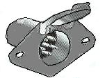
Below are pictures of the basic or most commonly used 4-Wire connector. You'll notice the connector on the right has three exposed or "male" post and the left connector has three "female" sockets. The other male/female pole is the ground. The connector with the three exposed poles or male connector is for the trailer side and the connector with the three female poles is for the vehicle side. The reason for this is because your vehicles electrical circuit will be energized anytime the ignition is on. So if you do not have a trailer or RV connected up to your vehicle, you wouldn't want live circuitry exposed which could touch metal objects and cause a short circuit. Therefore the vehicle side should always be the female connector and your trailer/RV should be the male connector.
FEMALE CONNECTOR___________________________________MALE CONNECTOR


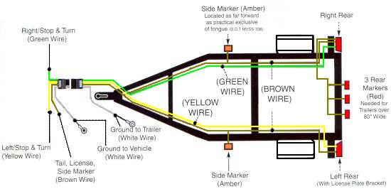
So in reference to the diagram below, the vehicle wiring or female connector is on the left and the trailer/RV wiring or male connector is on the right.
If your looking at the connectors as shown above, from left to right, the color codes will be as follows:
GREEN = Right Stop/Turn Lights
YELLOW = Left Stop/Turn Lights
BROWN = Tail/Running/License Lights
WHITE = Ground

When wiring your trailer, be sure to route your wiring so that all wires are tucked in and away from anything that could rub or catch on them. If your trailer is constructed of square tubing, I find that running your wires through the inside of the tubing makes for a much cleaner appearance and helps to protect the wiring as well. If your frame does not have pre-drilled holes, then it might be a little bit more work drilling holes and fishing out your wires, but you will be much more happier with the results. Be sure to seal your holes when done to prevent water from filling up your frame.
If you have a U-Channel or angle iron construction, then you can purchase specially made clips from most automotive stores that attach to the frame which will keep your wiring tight inside the frame and out of the way.
6-Wire Connectors
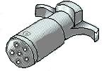
To wire a trailer, the first step is to determine what components on the trailer need wiring. The 4-way above is a basic and most common scenario, but what if you have more items that require wiring. Of course the more items you have the more poles you will need on your connector. The 6-wire connector shown here has 2 additional poles. One is for electric brakes and the other pole is a 12v source for anything else requiring electric.
Be sure to follow your vehicles operating manual for instructions on how to make proper connections when using any of these type connectors. Although most manufacturers use a standard color code, there are going to be those few that could stray from the norm.


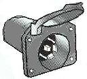
This is a diagram of a standard color code for the most common trailers or RV using a 6-wire connector. You will notice a difference between the male/female part of a multi-pole connector. Instead of the female going onto the vehicle, now the male is going on to the vehicle. This is because the "plug" mounting onto the vehicle has a cover which protects the prongs from touching other metal objects and from the elements so they don't rust. Then the trailer connector is now female which also provides protection when not in use.

Standard Color Code
GREEN = Right Stop/Turn Lights
YELLOW = Left Stop/Turn Lights
BROWN = Tail/Running/License Lights
BLUE = Electric Brakes
RED = Battery (12 Volts)
WHITE = Ground
7-Wire Connectors


When you wire a trailer with a 7 pole connector, you have one additional circuit than the 6 pole. This circuit is a back-up or also known as an auxilliary feed. What this circuit gives you is an extra 12v source that is usually fed off of dedicated batteries and is fused seperatly. This circuit is commonly used for the RV trailer which has a 12v circuit ran throughout and allows you to use lights and small loads while your connected to your RV and cannot be connected to an outside 120v source.

Standard Color Code
GREEN = Right Stop/Turn Lights
YELLOW = Left Stop/Turn Lights
BROWN = Tail/Running/License Lights
BLUE = Electric Brakes
RED = Battery (12 Volts)
ORANGE = Backup/Auxillary Power
WHITE = Ground


