Wire An Outlet
How to wire an outlet. Standard outlets are also known as duplex receptacles. There are a few options to choose from when you wire a receptacle. Most are wired so they are hot at all times but some are wired so they are switched off and on. You can also wire outlets so that only the top or bottom receptacle is hot at all times and the other is switched.
To wire a receptacle to be hot at all times or both receptacles to be switched requires a 3-wire cable. To wire an outlet so that only the top or bottom receptacle is switched and the other receptacle remains hot all the time, requires a 4 wire cable
You need to know up front which scenario you prefer if your wiring a new circuit. If you are just replacing an old outlet with a new one then the instructions on this page will help you identify which scenario you are dealing with based on the number of wires that are connected to your old outlet.
The diagram below will show how a standard "Switched" duplex receptacle is wired. In this diagram, both top and bottom receptacles are switched off & on. Take notice that only a 3-wire cable is needed to perform this circuit. The white wires tie together to complete the return side of the circuit while the black wire (hot wire) runs through the 2-way switch and out to the outlet.
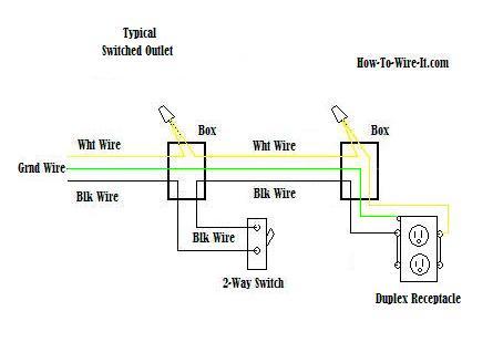
Duplex receptacles have (4) screws for termination points along with a green screw dedicated for ground. One side of the receptacle has (2) brass screws and the other side has (2) silver screws. The hot side of the circuit (black wire) should be wired to the brass screws while the neutral side of the circuit (white wire) should be wired to the silver screws.
You only need to connect to (1) screw on either side. If you look at the screws on one side you'll notice that a metal jumper connects the (2) screws together. This allows for both screws to be physically connected to each other so only (1) termination point is required.
Now in the diagram below, I have those jumpers labeled as J1 & J2. If you look closely you will notice that J1 has been split. This allows for a separate circuit to be wired to the other screw and allow the upper and lower receptacles to work independently of each other.
This circuit allows for the bottom receptacle to be switched while the top receptacle will remain hot at all times. To perform this circuit, you will need to use a 4-wire cable to allow for the extra circuit. 3-wire cable into the switch box and a 4-wire cable from the switch box the the outlet box.
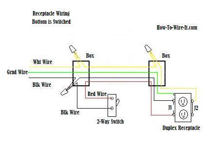
The black wire (hot wire) coming in from the left is the source power. It is tied together with a wire going to the switch and the black wire going to the outlet. The red wire (switched hot wire) going to the outlet, wires into the other side of the switch and the white wires (neutral), tie together to complete the return side of the circuit.
One of the most common wiring configurations your going to find with outlets are shown in the diagram below. These outlets are not switched. They are connected straight from the power source and are hot at all times.
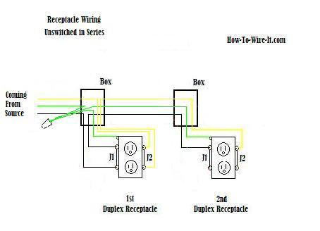
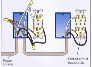
The diagram above shows (2) outlets wired in series and more outlets can be added to this circuit by wiring the 2nd outlet just like the 1st outlet to keep the circuit continuing on until you end the circuit at the last outlet. Now some electricians will use a (1)wire jumper from the outlet and wire nut together the circuits inside the box, but I prefer to use the screws on the outlet for a more secure connection. So if you are just replacing an outlet, I would recommend taking the wires off of the old outlet one at a time and putting that wire in the identical position on the new outlet.
The diagram below is the same as above but this circuit is switching the outlets.
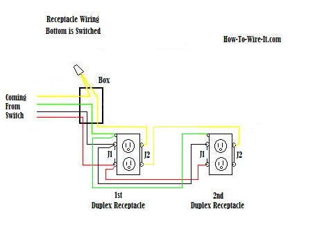
The box for the 2nd outlet was removed from the diagram for simplicity reasons. The 1st box gets very crowded in this circumstance but I am sure you can still get the concept. The same goes here as the unswitched circuit earlier if you have or are adding additional outlets to this type of circuit.
Above diagram circuit shows power coming from the switch and the below diagram shows power coming in from the one outlet box.
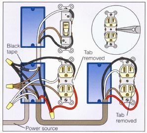
Step-by-Step procedure for replacing an existing outlet/receptacle.
Replacing an electrical outlet is a relatively straightforward task, but it's important to follow safety guidelines and turn off the power before you start. If you're not comfortable working with electricity, it's best to hire a professional electrician. Here's a step-by-step guide on how to replace an outlet:
Materials you'll need:
- New electrical outlet
- Screwdriver
- Voltage tester
- Wire stripper (if needed)
- Wire nuts (if needed)
- Outlet cover plate (if needed)
- Camera (Phone)
Here's the process:
- Turn off the Power: Go to your circuit breaker panel and switch off the circuit that corresponds to the outlet you're replacing. Double-check that the power is off using a voltage tester.
- Remove the Old Outlet: Use a screwdriver to remove the cover plate and then unscrew the outlet from the electrical box. Gently pull the outlet out, but don't disconnect any wires yet.
- Note the Wiring: Take a picture or make a note of how the wires are connected to the old outlet. You'll want to connect the new outlet in the same way.
- Disconnect Wires: Loosen the screws holding the wires in place on the old outlet. Carefully disconnect the wires and remove the old outlet.
- Prepare New Outlet: If the wires are still attached to the old outlet, remove them. Then, prepare the new outlet by loosening the screws on the sides of the outlet that hold the wires.
- Connect Wires to New Outlet: Connect the wires to the corresponding terminals on the new outlet. Typically, the black wire connects to the brass or darker screw, the white wire connects to the silver or lighter screw, and the green/bare wire connects to the grounding screw.
- Secure New Outlet: Gently push the wires and the new outlet back into the electrical box. Screw the outlet to the box using the screws provided with the outlet.
- Test the Outlet: Turn the circuit back on at the breaker panel. Use a voltage tester to ensure that the wires are live. Then, test the new outlet by plugging in a device to make sure it works.
- Cover Plate: If the new outlet is working properly, you can attach a new cover plate.
Remember, electrical safety is crucial. Always turn off the power before working on electrical components and use proper tools and techniques.
If you're not confident in your abilities, it's best to consult a professional
electrician to ensure a safe and proper installation.
View this video for a basic outlet change-out.


